Cathodic Protection - Monitoring and Maintenance

This is the sixth in a series of presentations by the South East Branch of PIG in the field of external pipe corrosion and cathodic protection.

This presentation explains the requirements and the practicalities of pipeline cathodic protection monitoring and maintenance for non-specialists.

It explains why the monitoring is necessary and what maintenance is recommended. The main pipeline above-ground survey techniques are discussed.

An example of the very latest technical developments in the reporting of routine monitoring and maintenance surveys is given.

IEEE Transactions on Power Delivery

Corroconsult’s Technical Director is a co-author of a new paper published in the IEEE Transactions on Power Delivery.  It was published on 09 April 2022.

The paper is a collaboration between Dr. David Boteler (Land and Minerals Sector,  Natural Resources, Ottawa, Canada), Prof. C. Charalambos (University of Cyprus, Nicosia, Cyprus) and Ken Lax (Corroconsult UK Ltd).

Previously unexplained instances of AC corrosion may be due to the effects of harmonics, which may not have been taken into account in the mathematical modelling and the interference mitigation design.  The presence of harmonics may not be apparent when taking voltage and current density measurements.

The paper gives a worked example of how to perform the calculations, which will be helpful for cathodic protection and pipeline electrical interference specialists.

Abstract:

Electromagnetic interference to pipelines and railways from AC sources has long been a cause for concern. Methods and standards have evolved to enable calculations of the voltages produced under different conditions. These take into account the AC frequency, the soil resistivity and the pipeline characteristics. However, the approximations presented in some standards fail to take into account the phase relationship of the currents in the AC conductors and how that affects the induced currents in the earth. This paper re-examines these issues by introducing a revised complex image method for 3-phase systems that provides a simple and accurate way to include the influence of induced currents in calculations of the induced emf in nearby conductors. Normal positive sequence 3-phase currents produce fields in neighbouring conductors that tend to cancel. For the associated image currents in the earth, the cancellation is so complete that they have no influence on the induced emf. A different situation occurs with the zero sequence currents that occur during fault conditions and triplen harmonics. These currents are in phase, so there is none of the cancelling effect and the contributions from each conductor add to give a larger induced emf in a neighbouring conductor.


Published in: IEEE Transactions on Power Delivery ( Volume: 37, Issue: 2, April 2022)

Page(s): 851 - 859

Date of Publication: 09 April 2021

ISSN Information:

DOI: 10.1109/TPWRD.2021.3072355


Contact Corroconsult UK Ltd for further information.

Exploring alternatives to the 4 Pin Wenner Soil Resistivity Method

Introduction

The Wenner four-pin method is the most widely recognised method for soil resistivity testing, using four pins at equal distance from each other along a straight line. This method has been primarily used in geological surveying since it was first developed in 1915 by Dr. Frank Wenner.

Beyond Wenner’s initial work there have been several developments since, identifying proven alternative methods for measuring soil resistivity.

This post has been put together noting the key factors and necessary information for three of the lesser known methods of soil resistivity testing.


Equatorial Dipole-Dipole Soil Resistivity

  • To a depth of 0.5m, with a dipole length of 1m, the depth curve sensitivity is considerably higher than the standard 4 pin Wenner method.

  • At a depth greater than 0.5m, the sensitivity-depth-curve decreases exponentially.

  • The required maximum depth reading shall not exceed 2.5 metres (due to loss of sensitivity).

  • A length of 0.5m with a dipole length of 0.3m provides the most sensitive-depth-curve.

  • Evidently, Equatorial Dipole-Dipole soil resistivity testing is most efficient at shallower depths with shorter dipole lengths.

  • With this method, you can penetrate further into the ground than the dipole-dipole standard array (so long as the length of the survey line is the same).

  • Although the equatorial array penetrates further into the ground, doing so will generate a loss in signal as the depth is expanded, which greatly limits its use.

  • This method is incredibly useful for situations where multiple readings of top-surface soil is required to a maximum depth of 2.5 metres.

Summary

Ideal for shallow depths requiring highly sensitive applications out in the field.


Wenner Schlumberger Soil Resistivity

  • A combination of the Wenner (most widely used method for soil resistivity and earthing purposes) and Schlumberger methods (high voltage signal, less sensitive.)

  • A large difference between this method and the more commonly know ‘Wenner’ method is that using Wenner, the pins are all equally distanced apart whereas in Schlumberger, the pins are not equally distanced and primarily, only two electrodes are moved to take a new reading whereas using Wenner, all four electrodes need to be moved to take a new reading.

  • This method of soil resistivity testing is best suited to increased depth requirments due to the high voltage signal.

  • Less applicable for shallower, more sensitive operations.

  • More practical to use when the task is to plot soil resistivity at several different depths.

  • Best suited for ground water and aggregate mineral terrain.

  • This method also takes less time to deploy than the standard Wenner array when changing pin spacing (i.e. moving two outer pins as opposed to all four pins).

Summary

Ideal for greater depths, with reduction in time spent altering pin spacings when compared to standard 4 Pin Wenner technique.


Dipole-Dipole Soil Resistivity

  • A dipole is a pair of oppositely charged electrodes that are so close together that the electrical field forms a single electrical field rather than a field from 2 different electric poles.

  • To conduct a survey using the dipole-dipole method, you place a large number of electrode stakes out with equal spacing between the stakes. i.e. 100 electrodes spaced 1 metre apart – This would generate a 99 metre long profile of the surveyed area to a depth of 1 metre.

  • To collect the high number of depth samples from the pin array, specialist equipment with a multiple core harness is required.

  • The apparent resistivity data is plotted at the midpoint between the 2 dipoles and at a depth half the distance between the 2 dipoles.

  • Typically 99 readings are measured and stored in approximately 15 minutes (this excludes the installation of the pin array and connection of the cable harness).

Summary

Ideal for high sensitivity measurement at increased depths. However, specialist equipment is necessary.

A Pipeline Designer's Guide to Cathodic Protection

As part of our ongoing free webinar series with The Pipeline Industries Guild, our latest presentation “Pipeline Designer’s Guide to Cathodic Protection” is now available on YouTube.

The aim of the presentation is to provide information to pipeline designers on the factors that can influence the effectiveness of the external corrosion protection system - coatings, cathodic protection and electrical interference.

The technical information is given in such a way that it is understandable to people that are not corrosion specialists.

Beginners' Guide to Cathodic Protection

This presentation was made by Ken Lax, Technical Director of Corroconsult, on behalf of the Pipeline Industries Guild (PIG) Onshore Panel as part of their ongoing free webinar series.

The presentation is intended for non-specialists to provide an overview of cathodic protection and stray current corrosion.

No electrical or electrochemical knowledge is assumed.

The presentation is non-mathematical and with only a sprinkling of science. It is a description of the processes, rather than a technical analysis.

The presentation covers the following;

  • Why steel corrodes

  • The role of coatings

  • Pipeline Cathodic Protection - General Description

  • Cathodic Protection - Galvanic / Sacrificial Anodes

  • Cathodic Protection - Impressed Current

  • Efffects of DC Stray Currents on External Corrosion

  • Effects of Induced AC on External Corrosion

ISO 21857 - Evaluating DC Stray Current Voltages

ISO 21857 - Evaluating DC Stray Current Voltages

Interference from dc traction systems can result in pipe-to-soil potentials outside of the acceptable limits.

The Q method is an established procedure for evaluating the time varying potentials and empirical guidelines have been developed to allow a judgement of the corrosion risk caused by the interference.

The method can be used to evaluate current densities as well as potentials.

The Importance of Electrical Isolation

Defining "Electrical Isolation" for a Cathodic Protection System

With respect to cathodic protection systems, the term "electrical isolation" relates to confining the (cathodic) protective current to the structure being protected.

In terms of electrical separation this could mean isolating;

  • Two (or more) cathodic protection systems from one another
  • Buried / immersed structures from above ground appurtenances
  • Cathodically protected structures from earthing systems
  • Owner / Operator interfaces

Electrical isolation is a key factor in the successful application of cathodic protection where it has been included at the design stage. For the purposes of this blog article we assume that the structure is intended to be electrically isolated.

That is not to say that electrical isolation is always required, as long as the designed system has taken this into account.

There are times when it may not be desirable, or even practical, to isolate protected from unprotected structures. Examples are refineries, industrial plants, large tank farms and similar complex facilities. 

How to Electrically Isolate the Cathodically Protected Structure

Commercial fittings for providing electrical isolation of pipework include;

  • Insulating Flange Kits (IFK)
  • Monolithic Isolation Joints (IJ)
  • Non-metallic pipe sections

Cathodically protected structures can be electrically isolated from earthing systems via;

  • Decoupling Devices

Other solutions, e.g. non-conductive membranes, are available as methods of electrical isolation depending on the system in question.

Insulating Flange Kits (IFK)

Insulating Flange Kit (Exploded View) resized.jpg

The kit comprises of the following;

  • Insulating Gasket
  • Non-Metallic Sleeves for Assembly Bolts
  • Non-Metallic Washers
  • Metallic Washers
  • Nuts & Bolts

Monolithic Isolation Joints (IJ)

Monolithic Isolation Joint resized.jpg

The isolation joint is fabricated as a ready to install section of pipework.

The joint consists of;

  • Forged Rings
  • External Coating
  • Internal Coating
  • Adhesive Sealant
  • Di-Electric Filler
  • Insulating Rings
  • O Rings

Decoupling Devices

Corroconsult recommend only solid-state devices, as this eliminates the maintenance requirements and hazardous electrolytes of electrochemical polarisation cells.

acdd.jpg

Solid-state DC decoupling devices can be used for;

  • Electrically isolating from from utility earthing (grounding) systems
  • Electrically isolating from electrical equipment earthing (grounding) systems
  • Induced AC voltage mitigation
  • Isolation joint protection

How can electrical isolation be compromised?

Incorrect Installation

An incomplete kit installation for an IFK will result in the flanged joint being electrically continuous.

Earthing / Grounding

The most common failure of installed electrical isolation is through incorrect earthing of cathodically protected structures.

DCVG Survey - A Beginner's Guide [Part 1]

Direct Current Voltage Gradient [DCVG] Survey

Introduction

This non-intrusive, above ground survey allows the operator to identify the location of coating defects (holidays).

We are pleased to announce the first uploaded animation to our YouTube channel (shown within this post).

The YouTube video represents the first instalment within a series. Its purpose is to give an introductory overview to people not familiar with the technique e.g. asset owners, operators, supervisors.

Recognition within International Standards for Buried Pipelines

The technique is an approved ECDA (External Corrosion Direct Assessment) method as detailed in ANSI / NACE Standard Practice SP 0502-2010.

DCVG is also listed as an above-ground survey used to assess the coating condition and to locate coating defects within:

  • BS EN 13509:2003 - Cathodic protection measurement techniques
  • BS EN ISO 15589-1:2017. Petroleum, petrochemical and natural gas industries. Cathodic protection of pipeline systems. On-land pipelines

All DCVG surveys should be undertaken by competent and qualified personnel in accordance with BS EN ISO 15257:2017 - Cathodic protection - Competence levels of cathodic protection persons.


This short animation shows the technique to be utilised for a DCVG (Direct Current Voltage Gradient) survey using an analogue voltmeter and matched electrodes.

The video covers the basic methodology in identifying, centering and measuring coating defects (holidays) in the field [OL/RE Potential]

This "How To" guide is intended for asset owners, operators and supervisors that may not be familiar with the technique.


An Overview of the ECDA Process

What does ECDA mean?

ECDA is the commonly used acronym for External Corrosion Direct Assessment. The process has been developed for buried onshore ferrous pipeline systems. ECDA was created as a process for improving pipeline safety. Its primary purpose being to prevent future external corrosion.

Whilst this post attempts to provide an overview of the ECDA process, it is imperative that it is tailored each time to address specific requirements of individual pipeline systems.

What are the main steps of the ECDA Process?

There are four main steps to the ECDA Process, these are;

  • Pre-Assessment [Desktop Study]
  • Indirect Assessment [Above Ground / Non-Intrusive Surveys]
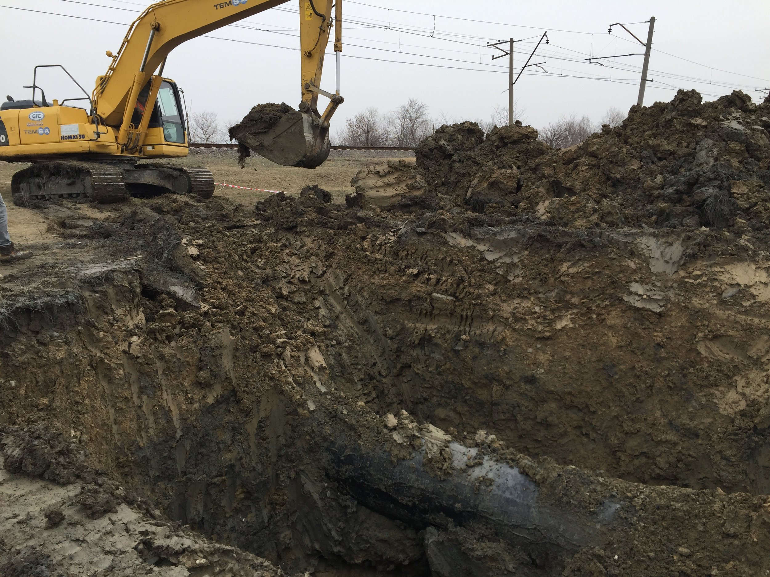
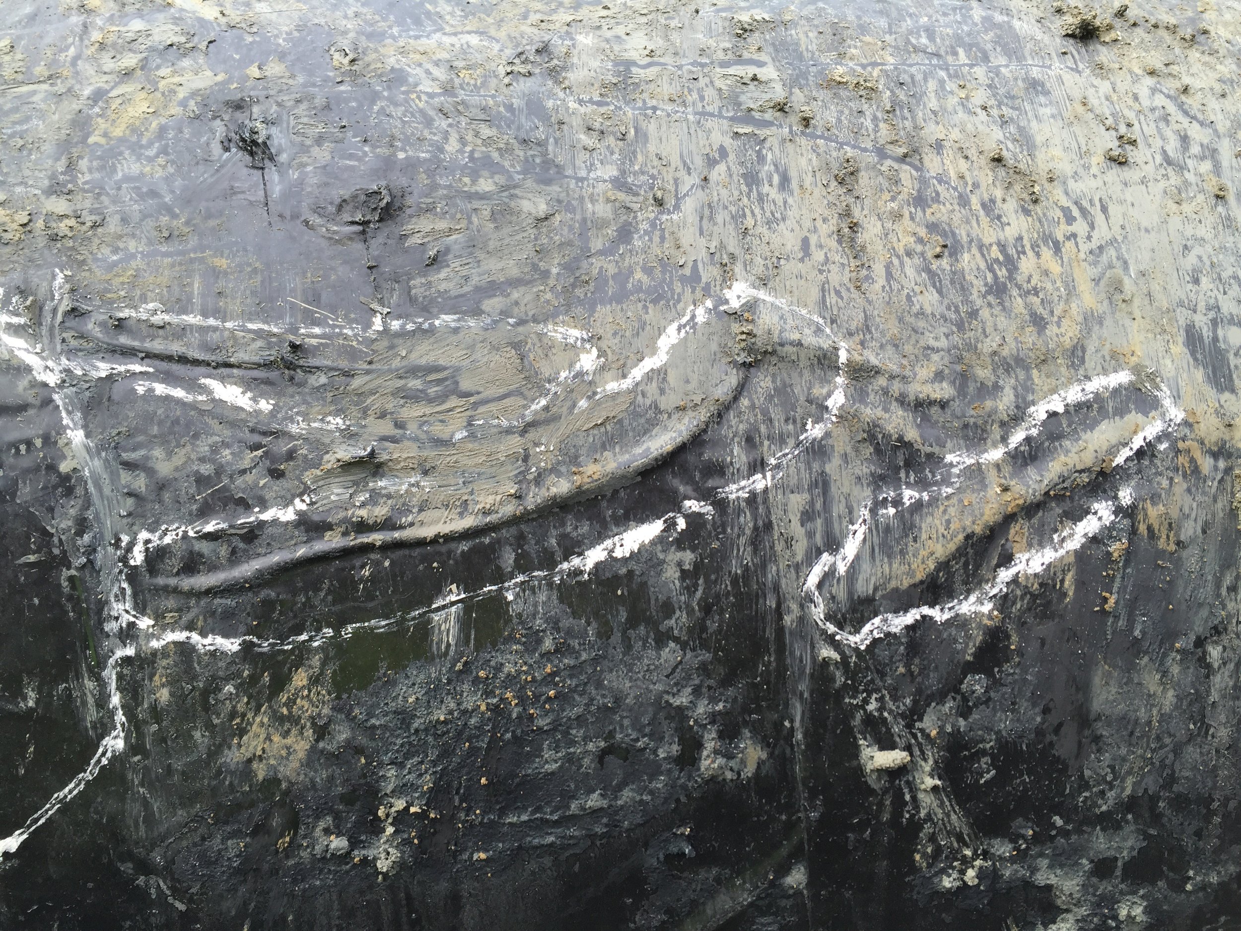
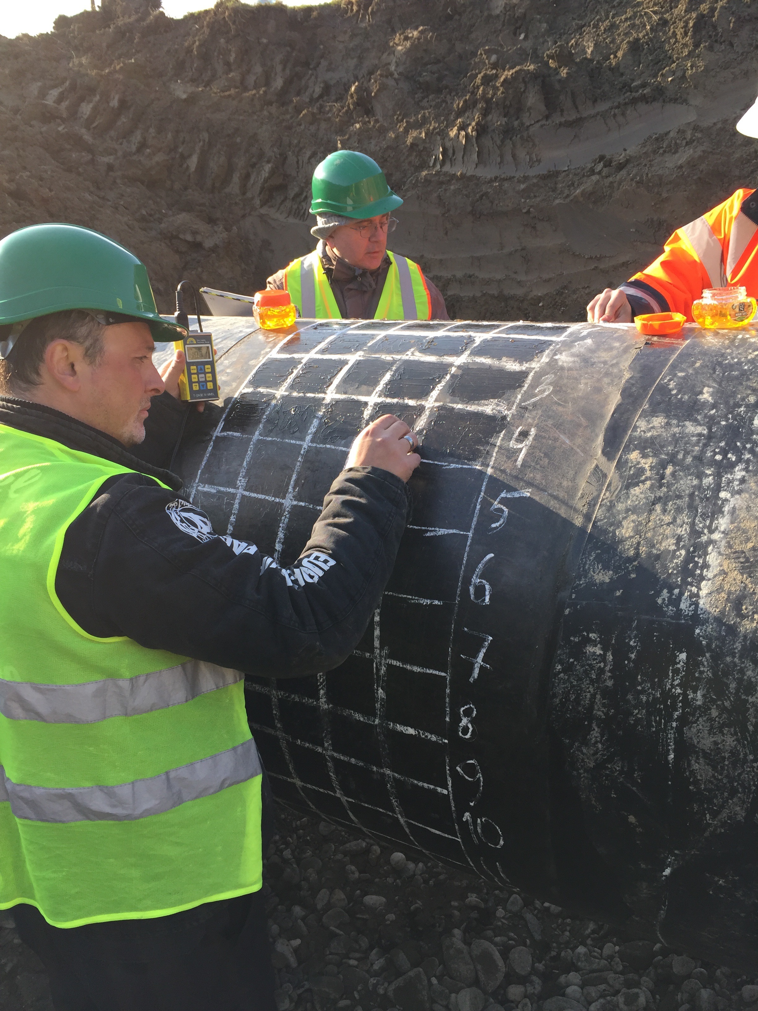
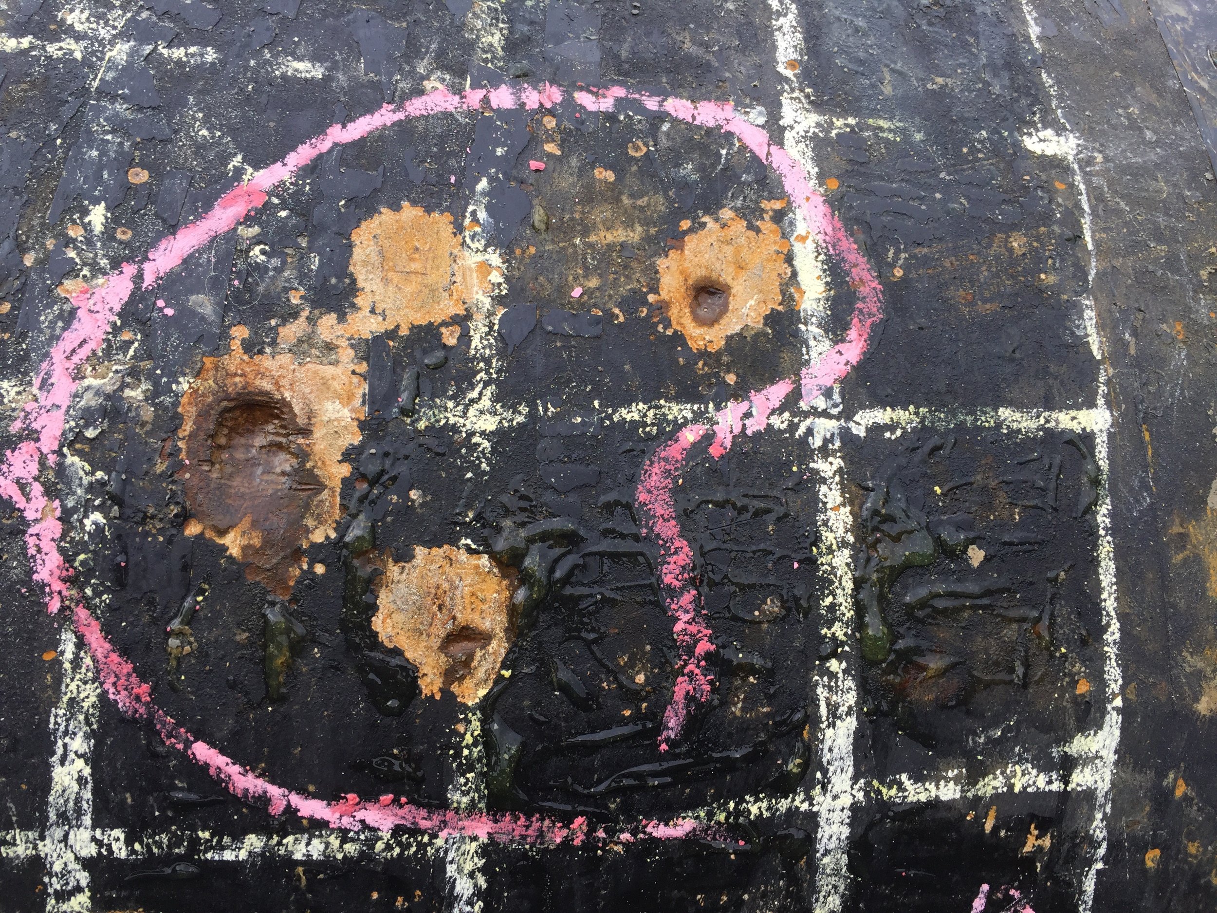
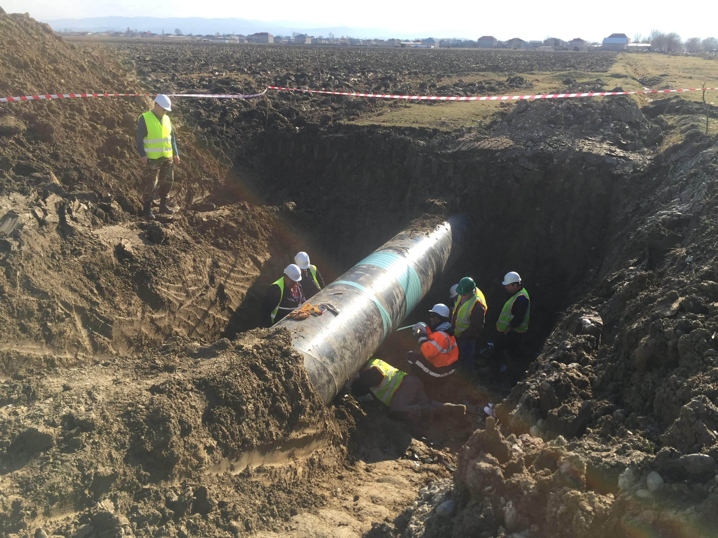
  • Direct Assessment [Bellhole Excavation & Testing]
  • Post Assessment [Calculation & Reporting]

The flow diagram below shows a general approach to the ECDA Process - evaluation methods may include, but are not limited to those shown here.


Pre-Assessment

Pipe Related

  • Material
  • Diameter
  • Wall Thickness
  • Year Manufactured
  • Seam Type
  • Bare Pipe Sections

Construction Related

  • Year Installed
  • Route Changes / Modifications
  • Construction Practices
  • Locations of Valves, Clamps, Insultaing Joints etc
  • Locations of and Construction Methods used at Casings
  • Locations of Bends including Miter Bends and Wrinkle Bends
  • Depth of Cover
  • Underwater Sections / River Crossings
  • Locations of River Weights and Anchors
  • Proximity to other Pipelines, Structures, HV Transmission Lines, Rail Crossings

Soils / Environmental

  • Soil Characteristics / Types
  • Drainage
  • Topography
  • Land Use (Current and Past)
  • Frozen Ground

Corrosion Control

  • CP System Type (Anodes, Rectifiers and Locations)
  • Stray Current Sources / Locations
  • Test Point Locations (or Pipe Access Points)
  • CP Evaluation Criteria
  • CP Maintenance History
  • Years without CP Applied
  • Coating Type – Pipe
  • Coating Type – Joints
  • Coating Condition
  • Current Demand
  • CP Survey Data / History

Operational Data

  • Pipe Operating Temperature
  • Operating Stress Levels and Fluctuations
  • Monitoring Programs (Coupons, patrol, Leak Surveys etc)
  • Repair History / Records
  • Leak / Rupture History
  • Evidence of Microbiologically Influenced Corrosion (MIC)
  • Type / Frequency of Third Party Damage
  • Hydrotest Dates / Pressures

Indirect Assessment

TR & Groundbed Functionality Checks

  • TR Output Current
  • TR Output Voltage
  • Drain Point Potential measurement
  • Groundbed Output Capabilities

CIPS (Close Interval Potential Survey)

  • Synchronously Interrupted
  • On Potential Measurement
  • Instant Off Potential Measurement

DCVG (Direct Current Voltage Gradient) Survey

  • Synchronously Interrupted
  • OL / RE Measurement
  • % IR at Defect Calculation

Additional Information Collated

  • GPS Coordinates recorded for key features and locations
  • Distance measurement of key features and locations
  • Photographic records taken for key features
  • a.c. potentials measured at all test facilities
  • Overview of condition of test facilities and associated connections
  • Data logging at identified / possible sources of Stray Current

Direct Assessment

Locations for excavation shall be selected based on the information gleaned from the pre-assessment and indirect assessment procedures.

A minimum of at least one trial pit should  be excavated to clarify the effectiveness of the first two procedures.


Post Assessment

All data obtained during the survey activities is provided, generally in both graphical and tabular formats (where appropriate), as well as photographic records, etc.