The following paper was presented at BHR Group's 1st Interational Conference for Pipeline Integrity – Schipol, The Netherlands – 5th – 7th November 2008.
The paper was authored jointly by Richard Lindley and Ken Lax, and presented by Richard at the conference.
DISCLAIMER: All information, references to Standards and / or criteria correct at time of paper.
ABSTRACT
A description is provided of the above ground measurements that should be made in the evaluation of pipelines that are to be rehabilitated. Simple measurements, carried out by trained and competent personnel, can provide quality data to enable decisions to be made for pipeline rehabilitation.
The importance of data integrity is considered and the use of competent personnel to collect data.
Data management and data analysis methods are discussed and an example of the weighting factors for a Priority Matrix to provide an overall risk for each section of the pipe is provided.
INTRODUCTION
When a pipeline is considered for rehabilitation it is inevitably because the pipeline is believed to be in a poor condition, usually due to neglect over the operating life.
On this basis it is usually safe to assume that:
- Whatever coating there was has now deteriorated to the point where it is of no benefit
- Cathodic protection was never properly applied, maintained, or implemented
- Construction records are no longer available
In certain countries you will also be safe to assume that the field joints are suspect and were never properly coated.
Add to this the unrealistic expectations of lay personnel regarding the cost of pipeline rehabilitation and repairs and there is a huge uncertainty over the prospects for rehabilitation.
Contrary to the opinion of many large pipeline contractors and consultancy groups the best way to rehabilitate a pipeline may not be to dig, expose it all and re-wrap it. Aged pipelines, even those suffering from neglect, are not usually uniformly bad and in need of replacement.
The above ground measurement and inspection techniques described in this paper will enable firm engineering decisions to be made regarding pipeline repairs, coating replacement, and cathodic protection.
International standards and recommendations are not always helpful in providing guidance. These documents should be treated with caution and recognised for what they are. In the case of standards they are a guide for specialists to employ, not text books. Recommended practices are the opinions of a committee based on their experience and do not have the provenance of a standard.
A good in-line inspection tool can provide the best available information on remaining wall thickness but some tools exaggerate the capabilities of the analysis to provide details on wall thickness, coating disbondment and cathodic protection statements. As in all cases the tool capabilities should be carefully reviewed and verified before committing to major expense.
This paper deals with the options available for above ground inspection. Above ground inspection is sometimes the only tools that is available to prepare an assessment for rehabilitation and can be used as a stand-alone or as a complimentary set of data for rehabilitation.
It is always good for research and progress to develop new techniques and advanced analysis but we can achieve a great deal if we properly employ the known and existing techniques.
There is no universal solution to pipeline rehabilitation works. Each section of the pipeline has to be considered on its own merits.
The paper does not make any prescriptive recommendations, its purpose is to emphasise that when above ground measurements are made by professionally competent personnel then the data can be used to determine the suitability of each section of pipeline for rehabilitation.
The techniques have been successfully applied to many pipelines around the world, even those that the “experts” said could not be rehabilitated.
EXTERNAL CORROSION
Whilst above ground measurements alone will provide no indication as to the internal condition of the pipe, with no available alternative, an assessment of the external condition of the pipeline can provide vital information as to the feasibility of rehabilitation.
Mechanisms
The following section details the principal mechanisms for external corrosion to occur on a pipeline.
Coating Failure
The purpose of a coating is to provide a high resistance barrier between the pipe and its surrounding environment.
Where the coating is damaged, active corrosion will occur in the absence of an operational cathodic protection system.
Where effective cathodic protection is applied, the corrosion process at a coating defect, or holiday, can be slowed to an almost negligible rate.
Soil Conditions
Soil resistivity measurements are made to provide an indication of the soil corrosivity and for use in anode groundbed and attenuation calculations.
Soil corrosivity is classified by the British Standard BS7361 (1) as:
· 0 – 10 ohm·m severely corrosive
· 10 – 50 ohm·m corrosive
· 50 – 100 ohm·m moderately corrosive
· > 100 ohm·m slightly corrosive
Resistivity is not the only factor affecting corrosion, other factors which may be considered include;
- pH
- total acidity
- aeration
- moisture content
- soil type
- soil permeability and composition
- heterogeneity
Mechanical Damage
It is not uncommon that during construction, or through third party excavation, the pipeline can be damaged. At best this can mean removal of the coating, at worst it can mean scoring of the metal itself.
If this damage is not identified at the time, or subsequently reported and repaired, these locations will be subject to corrosion.
On pressurised pipelines, the maximum allowable operating pressure is calculated using the pipe material and its initial wall thickness. If metal loss occurs, either directly, or through corrosion, than naturally there is a reduction in the allowable operating pressures.
DC Stray Currents
DC stray currents will create metal loss, not at the point where the current enters the pipe, but at the point that it leaves the pipe.
1 Amp DC leaving a steel pipe will cause 9.1 kg of metal loss per year. And whilst the current leaving the pipe is usually of a significantly smaller magnitude than this, they can be increased due to sources of DC stray current, including;
- DC transit systems, such as railways, trams etc
- Third party cathodic protection systems
- Welding activity
- Mining
- Telluric currents
AC Influence
AC interference can present two main issues on a pipeline.
Firstly, is one of safety, as voltages above 15 VAC (2) can be considered as hazardous to personnel, through “Touch Potential”.
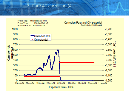
Secondly, it is only relatively recently that AC interference has truly been recognised as a potential cause for corrosion on well-coated pipelines.
The propensity for AC corrosion to occur can be classified by;
- Proximity to AC source
- Magnitude of AC source
- AC current density
- Ratio between DC and AC current densities
- Soil Type / Resistivity
- Levels of cathodic protection
ABOVE GROUND MEASUREMENTS
The purpose of the above ground measurements is to obtain enough quantifiable information with regard to the pipeline without the need for excavation.
The following section details several methods that can be combined to assess the pipeline condition, although their individual selection depends on both Client requirements and feasibility.
DCVG (Direct Current Voltage Gradient)
The purpose of a DCVG survey is to identify coating defect locations and, once located, to benchmark them against other coating defects on that pipeline.
The technique requires a source of DC current to be interrupted cyclically, either from an existing cathodic protection system, or a temporarily installed system. The pipeline is then traversed using two equally matched electrodes, and an analogue voltmeter, as shown in Figure 1.


